Posts

Final System

Image
THIS IS A VIDEO OF THE FINAL SYSTEM SHOWCASING THE PROCESS DEVELOPMENT OF IMAGE PROCESSING, TRAJECTORY PREDICTION AND ROBOT MOTION CONTROL.

Test - Relationship between Accuracy and Angle

Image
Hi, This blog will cover the results gained from testing the accuracy of the robot successfully hitting the puck at varying angles for both sides. Below is a graph of the results. Relationship between successfully hitting the puck at varying angles for both table sides. The robot had the most success hitting the puck when it bounced off the right side of the table greater than the left side for all three categories. Each category had a sample size of 10. The performance of the robot decreases with increasing angle. However, as the speed was not taken into consideration when conducting this test, some of the results may be a result of the robot not having enough time to react. For both sides, the robot had the most success of hitting the puck at an angle less than 50 ° a s the puck bounced multiple times, reducing its velocity and allowing the robot enough time to react with 83% success rate at right side and 50% on the left side. A possible reason for the difference betwee...

Test - Relationship between Accuracy and Speed

Image
Hi, This blog will cover the results gained from testing the accuracy of the robot successfully hitting the puck at varying speeds. Below is a graph of the results. Relationship between successfully hitting the puck at varying speeds The robot couldn't hit a moving puck with a velocity of over 250 cm/second as it didn't have enough time to react. Increasing the speed of the robot will not solve this problem as there will always be an initial delay before executing every motion commands due to the download approach that the ROS-Industrial driver provides for the ABB IRB 120. Although, the system prefers slower puck to allow enough time for the robot to react, a puck moving at a velocity of less than 50 cm/seconds reduced success rate to 16.6% with sample size of 6. A valid reason could be that as the puck cannot get enough acceleration to avoid being affected by physical properties like warping of the table, the direction of the puck is affected. The robot moves to th...

Implementing bounce trajectory algorithm

Image
Hi, I implemented the bounce trajectory that I developed in simulation to the final system. Bouncing the puck against the table sides reduced its velocity and thus gave the robot more time to react. Although the algorithm is far from perfect, I am glad that I developed this algorithm as the robot would at least move to an estimate future puck position. Possible reason for the error could be the bounce trajectory algorithm which assumes that there is no velocity lost after the puck hits the sides and thus would not alter the direction of travel. Another reason could be the vision of not localising the centre point of the puck properly in some areas of the table. Anyways, below is a video of the robot moving to a predicted future puck positions after a bounce(s). Video of bounce trajectory on final system Immanuel

Reducing waypoints to be downloaded

Image
Hi, I decided to use function compute_cartersian_path despite the results from comparing the duration of trajectories between this function and using the go function. Although, the go function generated shorter trajectory duration and removed the need of planning, both functions applied in the physical system produced similar results and was not capable of compensating with the the initial delay of the robot's motion. From testing time events from the previous posts, I figured that the robot averaged 1242ms from the the time that the puck is moving towards the robot and the time the robot gets to the predicted position. However, as I was using the go function, the average length of the trajectory points is 12 which the robot has to move to before reaching the prediction position. I figured that the current ROS drivers for the robot is to download all trajectory point-by-point before starting the robot's motion. Therefore, I explored ways to reduce the number of trajectory...

End-effector

Image
Hi, This blog will showcase the design of the end-effector that will be used in the final system. The picture below shows the two-part end-effector for easy mounting on the robot's tool flange. It was inspired from the original mallet that came with the table. The top part holds the 6 mm nut and has 4 mounting holes whilst the bottom part holds the screw. The total length of the end-effector is 118 mm and the bottom part has a diameter of 60 mm. Felt is also attached to the bottom of the end-effector to avoid scratching on the table's surface. End-effector Immanuel

Bug - ABB moves in multiple attempts

Image
Hi, I have discovered a behaviour that the ABB makes when attempting to hit a moving puck as shown in the video below. This behaviour is caused by having multiple predictions in one puck motion. Video of ABB attempting to hit the puck multiple times The logic of my current system is to take three puck positions, predict a future position and move the ABB to the predicted position. If there are still pre-recorded puck positions, the ABB will attempt to move. There are two ways that I explored to fix this problem: 1. Take more than three positions to reduce number of predictions in one puck motion. Although, this would delay the start of the robot's motion as more positions has to be recorded which is not ideal as using three positions would often yield the same predicted position as recording ten positions. Also, considering the delay I have encountered when sending a command to the ABB, I want to predict and move the ABB as soon as possible. 2. The second op...

Collision avoidance

Image
Hi, To avoid the robot from unexpectedly moving to unwanted positions, I created collision objects around the robot for safety measures. If a trajectory is created and it involves one of its way points to collide into the objects, the robot will not complete the trajectory and stop to the way point just before colliding. The video below showcases the robot's parts going red when colliding into the green objects. When setting a pose target, the robot will stop before colliding in both simulation and in the real-world. Video showing collision objects Immanuel

Time testing between events

Image
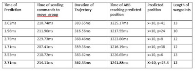
Hi, After playing around with the speed of the ABB, I wanted to find out what is still causing the delay between the point that the puck is moving towards the robot, trajectory prediction, the time of sending commands to the move_group node and to when the robot actually reaches that position. Below are my results from the investigation of five samplings. Testing Results As shown in the results, the robot reaches the predicted position an average of 1241.88ms after the puck is moving towards the robot. One possible cause for the initial delay of the robot's motion is having low computer performance which could slow down the process of finding a plan to perform on the robot. To remove doubt of the computer's performance, I did the same test but without running RViz as the simulator used almost 40% of the CPU. However, the results returned similar behaviour and averaged 1263.69ms from the time that the puck is moving towards the puck and the time when the robot actual...

Increasing robot's speed

Image
Hi, This week, I managed to increase the speed of the robot by switching parameters: has_velocity_limits and has_acceleration_limits to true within the joint_limits.yaml file that MoveIt! creates. The speed of the robot's joints can also be increased through this file. The image below shows the default yaml file. Default joint_limits.yaml I tested different velocity and acceleration to reduce the duration of the trajectory. I used values of 10, 15 and 20 within max_velocity and max_acceleration which reduced the duration of trajectories from 650ms with the default setting to an average of 350ms. I decided not to increase the speed further as it showed no difference in terms of successfully hitting the puck. Below are two videos to show the differences of the robot's speed from the default settings to turning off each of the joint's velocity and acceleration. Limited joint velocities & acceleration  Customised joint velocities & acceleration ...

Current Progress

Hi, This blog will be a quick rundown of my current progress with the final year project. With only a month to go left, I have to optimise my time and prioritise the main components of my project. The vision and trajectory prediction have been updated lately, therefore I don't plan on changing the methods and processes I have used until the final implementation. I decided not to use a raspberry pi as I want to have everything running on the Linux PC. In addition, I plan on not implementing the LEDs on the final setup as I believe that there is sufficient lighting in the room where the system is located. Immanuel

Comparison of IK functions

Image
Hi, In this blog, I will explain the functions that the Moveit! package provides to move the ABB to end-effector positions. Using MoveIt! KDL solver, I am able to move the robot to predicted y-coordinates given x-coordinates using my trajectory prediction algorithm. A function that I explored is compute_cartesian_path which plans a Cartesian path by specifying a list of waypoints for the end-effector to go through. Within the Moveit! package, the convention is to use metres, therefore, I chose a step size of 0.01 to move the robot between points at a resolution of 1cm. Below is a snippet of my code that implements the compute_cartesian_path function to move the robot to positions in  reference to the air-hockey table. Implementation of compute_cartesian_path function Sending trajectory commands from ROS to the robot's controller creates a small delay due to the implementation of the ABB driver of downloading trajectories instead of streaming them. It is difficult for t...

Real-time tracking and positioning

Image
Hi, In this blog, I will showcase two investigations that I have conducted to remove the doubt that my code is not the root of the delay issues that I have faced when sending trajectory commands to the robot's controller. To move the robot to the specified position I am using a function called compute_cartesian_path which computes and executes a plan of waypoints from its current pose to the target pose. The videos below illustrates a simple tracking of the puck and positions the end-effector to the y-coordinate of the puck. To avoid the robot from jittering, I appended 5 positions of the puck in a list and took the average of the list using mean and weighted average. As I am taking an average of positions, the robot may not initially exactly move to the puck's position, however, it will move there in the end. Tracking and Positioning using a mean average Tracking and Positioning using a weighted average As shown in the videos above, both investigations s...

Moving ABB by joint positions

Image
Hi, I cloned the official ROS-Industrial ABB experimental meta-package which offers various launch files to get started with the ABB IRB 120 using ROS such as connecting to the real robot. Using the moveit_planning_execution.launch provided by the package, I could connect to the real robot and run my own code. In addition, the robot's trajectory can be visualise in RViz before sending commands to the real robot. After playing around with the Moveit! Python Interface, I programmed the ABB IRB 120 by specifying a joint angle to rotate as shown in the video below. Although, I plan on only using this method at the start of the program to make the robot's tool flange parallel to the air-hockey table. Moving the ABB by joint positions If I don't specify the rotation before moving the robot to positions, the robot could possibly collide onto the table. The robot would look like the image below. Directly specifying position without making tool0 parallel to table ...

Creating static frame in ROS

Image
Hi, This week, I created a node that publishes a frame to reference the robot's end-effector positions. Following these tutorials , I succeeded in creating a static frame in ROS and learned about tf transforms. Coordinate Frame Tree Update 25/03/19 After playing around with tf transforms, I faced problems of converting poses between frames due to time issues i.e. the rate that each transforms are published. Therefore, I plan on using offsets for now to progress further on my project. In addition, I have 3-D printed mounts to fix the air-hockey table onto the table that the ABB is mounted on. This will remove the need of calibrating the system to find where the air-hockey table is in reference to the robot. Immanuel

Getting Started with ABB & ROS Industrial

Hi, I succeeded in following the tutorials found in the  abb/Tutorials  for installing and operating an ABB robot using the ROS Industrial interface. This tutorial covered multiple things: 1. Walk-through guide of installing the ROS Server code on the ABB robot controller and in RobotStudio. 2. Running the ABB ROS Server to execute motion commands sent from the ROS client node. I also followed this tutorial  to run motion commands from a Linux PC. This tutorial covered the commands that I needed to get started of moving the ABB in both RobotStudio and the physical robot. To enable the robot in RobotStudio from my Windows PC to move from commands sent by the ROS client in my Linux PC, I had to disable some firewall securities. Using these two web pages ( Google Forum  and  Allow Pings ), I was able to allow communication between two PCs. Looking at the rapid code provided by the abb/Tutorials, I figured that I needed to run the physical robot in...

Camera Setup - Updated

Image
Hi, This week, I updated the camera setup to implement with the overall system. After using the previous camera setup for a couple of weeks now, I found it to be fragile and often moved a lot. To progress with the project and actually get to use the real robot, I had to create a robust table frame that I plan to use in the final demo. Final CAD for Camera Setup Note: The brown table is where the ABB will be mounted on. It has the same dimension as the table that the ABB is currently mounted on. Physical Camera Setup  The image above shows the actual camera setup. I still have to print the part that the camera will be mounted on. In addition, the ABB is currently mounted on two pieces of 8mm thick MDF that contains holes for m8 bolts. I plan on using these holes to hold the table in place to make calibration between the table and the robot easier. Immanuel

Linear Regression - Bounce Trajectory 2

Image
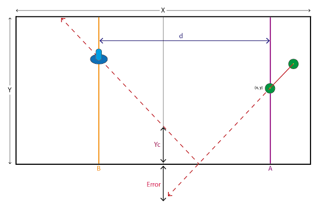
Hi, In the previous method, I described a method for handling bounce trajectories using Linear Regression. Below is an image showcasing another way to predict a bounce without swapping the axis and the need of creating new coordinates from the point that the slope intercepts the Y-axis. Code explained: 1. Calculate slope between atleast two points, as soon as the puck changes direction and is moving towards the ABB. 2. Using the slope, I predict the y position of the puck at the centre of the table. 3. If the prediction is greater than the table height,the error is calculated. 4. A new trajectory called Yc is created by reflecting the error from the end of the table. Video of two softbots playing with each other using two different methods Immanuel

Linear Regression - Bounce Trajectory 1

Image
Hi, In the previous post, I described a method for predicting a future puck position by using linear regression to calculate the slope between at least two points when the puck passes a specified x-coordinate. This method works well in simulation as the paddle could move instantaneously to intercept the puck at any given time. However, in the real-world, the ABB might not be able to move as quickly or as safely as I would want it to like the simulation. Therefore, instead of predicting the trajectory of a puck when it passes an x-coordinate, a possible solution is to predict as soon as the puck is moving towards the ABB so that the ABB does not have to move as fast. The problem with this method is handling possible bounces when the puck hits the table edges before a point that the ABB can intercept the puck. A possible solution to handle bounce trajectories is shown below. This method works by swapping the axis of the table and finding out the point that the slope interce...

Trajectory Prediction - Linear Regression

Image
Hi, If I know the coordinate of the puck within a period of time, I can calculate the change of the puck's y-coordinate in respect to its x-coordinate. Plotting multiple puck's positions in a graph shows the puck's direction of travel and most importantly, I can estimate a future position using the line of best fit, also called regression line. Below is an example of how I can predict the trajectory of the puck using equation: Y = mX + b Where; Y = mean of all y-coordinates X = mean of all x-coordinates m = slope of the line b = intercept point of line in the Y-axis Applying the knowledge gained of calculating linear regression using the least-square method and wonderful tutorials online, I have created a function to calculate m and b to predict a y-coordinate given an x-coordinate. Video of softbots playing with each other using two different methods The video below shows the paddles moving autonomously. Note that the paddle on the left i...